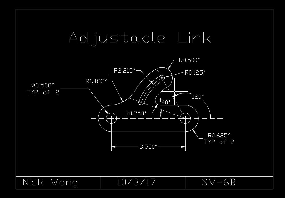
This drawing was a great challenge to overcome and draw because of the curve on the top half of the drawing and the angles and understanding what needed to be done in order to produce an accurate drawing of the adjustable link. I discovered that using tangent-tangent-radius needed to be utilized to make the curves of this drawing and using the polar tracking setting to make a specific angle.
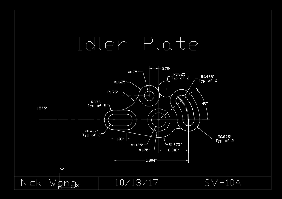
This single view drawing combined the skills of previous autocad methods, tangent-tangent-radius, and fillet to create the curves lines of the idler plate.
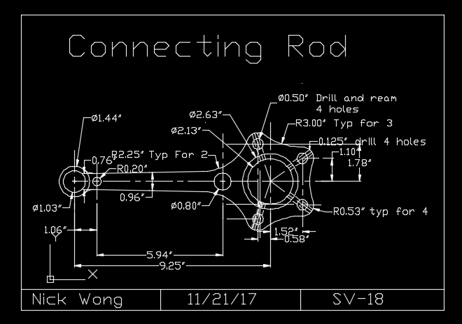
The connecting rod drawing became a difficult challenge to me due to all the circles and lines needed to be drawn accurately. It was easy to mess up the drawing if you have a few wrong measurements, which happened to me but I was able to find and change the wrong measurements before finishing it. This drawing consisted of using the fillet command, array for the circles, tangent-tangent-radius, and angled lines.
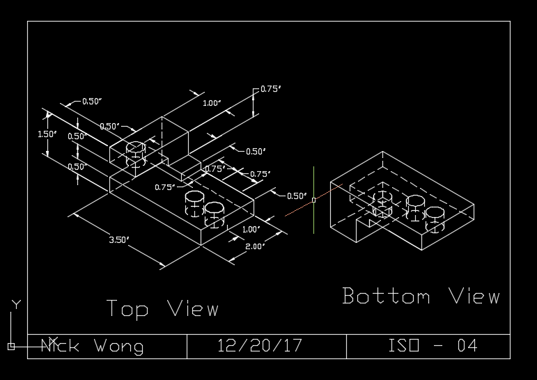
This isometric drawing consisted of learning how to read the top view and the placement of lines, especially for corners which needs 3 lines to produce an accurate top and bottom view. Also, we had to use "ellipse" to make "holes" in the drawing. By doing the top and bottom views, we are learning how to look at a drawing at a different view along with knowing where to place hidden lines.
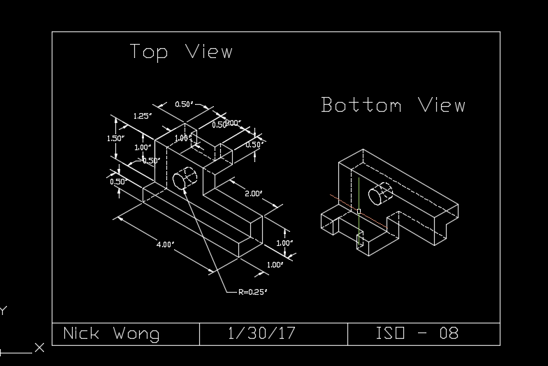
This iso drawing only gave the top view and not the bottom view, giving me a challenge on how to look and imagine what the bottom view looks like turning it 180 along with knowing where to place the hidden lines. I eventually figured all this out, learning that the hidden lines are the parts of the drawing that cannot be seen if you printed it out in 3D.
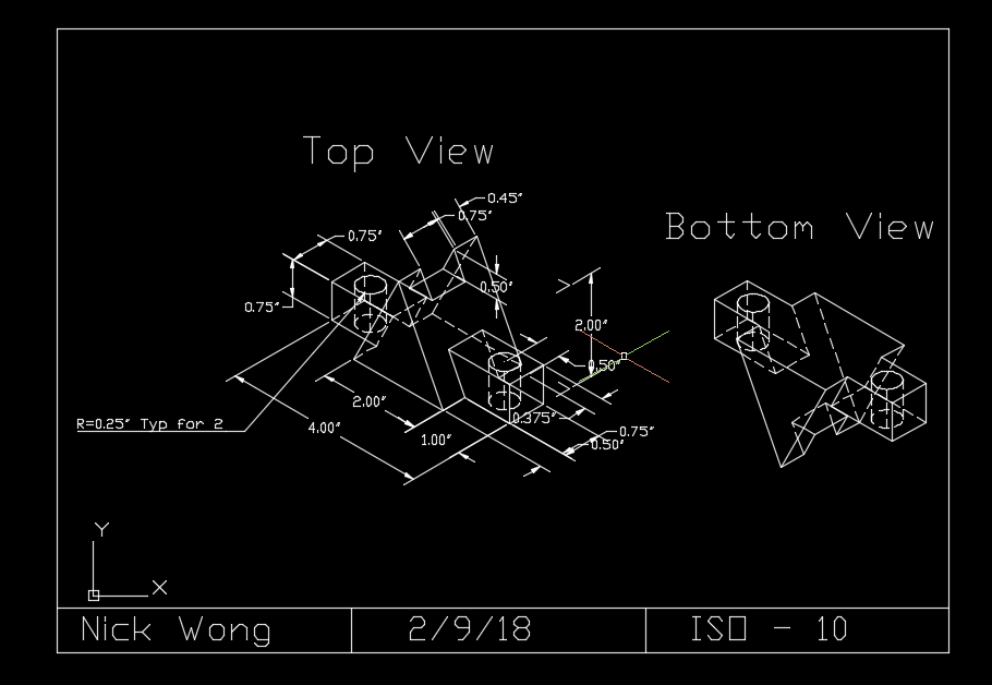
This drawing was a little difficult to do due to the two triangles in the middle and figuring out the measurements for each. Also, the support through the pyramid was difficult to produce but after paying closer attention to the drawing as whole, I was able to make the support accurately.
This was the first 3D drawing we did, learning the basics of how to make a simple room along with inserting the doors, windows, and the water closet. This drawing was just a way to get used to making 3D drawings.
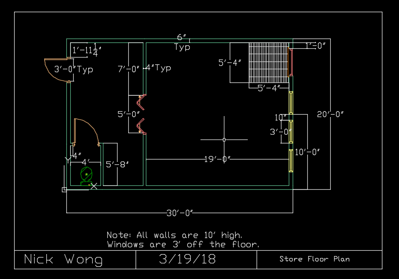
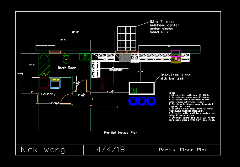
The partial floor plan started off as a challenge due to the wrong measurements given for the exterior walls. After that, everything was relatively simple with the rest of the walls, doors, and inserting the toilet, tub, sink, washer and dry cleaner. As for the cabinets, I had to open up to the CAD file and open up one of the files to insert a cabinet, copied it, then went back to the drawing and pasted the cabinet as a block.